[1] How is Electricity Transmitted?
In this section, we introduce the electrical systems we rely on every day, the types of power outages, and how we can handle them.
Now more than ever, electricity is an indispensable part of our society. The widespread destruction of disasters like the Great East Japan Earthquake of 2011 reminds us of the importance of electricity. When everything from refrigerators to production lines suddenly came to a halt, we felt a renewed appreciation for the electricity that we had taken for granted.
In recent years, the popularity of hybrid electric vehicles and fully electric vehicles has risen rapidly. But what will happen when a blackout occurs in this era where everything from our transportation infrastructure, computers and smartphones, street lighting, and kitchens rely on electricity? This section introduces the fundamentals of the electric power system and some basic knowledge about power outages and measures to cope with them. First, let’s look at how electricity works.
|How Power Companies Transmit Electricity
![]()
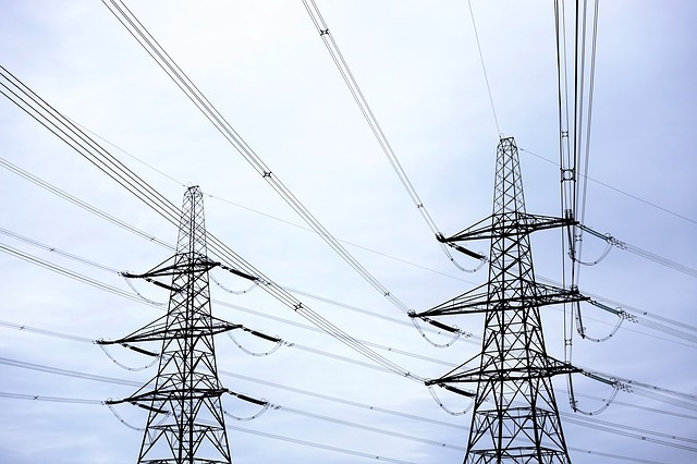
Generally speaking, electricity is generated at power plants operated by power companies. Electricity from a power plant passes through the power lines of transmission towers, also called pylons, then the voltage is decreased, or stepped-down, at transformer substations before being used to power factories and our homes.
The transmission lines that transmit electricity are usually in the form of overhead power lines. The standard and most common structure is the double circuit transmission line which is characterized by having two independent circuits aligned vertically on either side of the structure with each circuit made up of three sets of lines for a total of six transmission lines.
|Double Circuit Transmission Lines
![]() As the figure illustrates, double circuit transmission lines have an equal number of lines on each side. Rather than sending a “different” kind of electricity, each side sends the “same” electricity. There is a simple reason for this: reliability.
As the figure illustrates, double circuit transmission lines have an equal number of lines on each side. Rather than sending a “different” kind of electricity, each side sends the “same” electricity. There is a simple reason for this: reliability.
This mechanism enables one side to continue sending power even if an accident occurs where transmission is impossible due to damaged caused by a natural disaster, a bird or other wildlife, or by human error. In other words, using two circuits to transmit power increases reliability with the aim of preventing prolonged, wide-scale power outages.
Also if you look carefully, you can see that there is an electric wire at in the highest part of the tower. This electric wire is called an optical ground wire, and it is not for conveying electricity, but it serves as an arrester to attract lightning. It minimizes the likelihood of direct lightning strikes to the transmission lines.
Electric utilities make various efforts to increase the reliability of power transmission, but still, power outages occur. In the next section, we’ll introduce some types of power outages—some of which may surprise you!
[2] What Are the Types of Power Outages?
In the previous section, we looked at how power companies increase the reliability of their power transmission. However, it is impossible to prevent power outages entirely. In this section, let’s learn about power outages and other disturbances. By the way, did you know that there are various kinds of power failures?
There are, in fact, various “kinds” of outages. Here, as shown in the figure below, we’ll explain the three patterns of power disturbances using the scenario of a lightning strike affecting transmission line A.

![]()
(1) Dips (instantaneous voltage dips, brownout)
Electricity generated at the power plant is first transmitted via dual line then combines into a single line at a substation. Leaving the first substation, the line splits into two then is feed through the next substation. If lightning strikes transmission line A, the voltage on all the A, B, C, D lines receiving power from the same substation drops for a brief moment.
That “moment” is about 0.07 to 2 seconds. Electric utilities typically label such phenomena “dips.”
(2) Interruptions (momentary outage)
After lightning strikes line A causing a dip, the utility will disconnect line A, and then, after about a minute, power will regain transmission. This phenomenon, where power transmission on line A is restored following a momentary break in service, is defined by power companies as an “interruption.”
It may be a stretch to merely deem this an interruption on account of it generally taking about a minute to regain transmission. However, as the disruption lasts under a minute, utilities on purpose refrain from calling this a “power outage.”
(3) Power outage
The power company automatically restores power transmission to disconnected line A within a minute. If the voltage doesn’t stabilize even after power is restored, the power transmission on line A is stopped. After that, the utility will investigate the cause of the voltage problem, but line A will stay disconnected until the cause has been eliminated.
This situation, according to the utility, would constitute a “power outage” since the power has been stopped for more than one minute.
As described above, power companies define three types of power disturbances: dips (instantaneous voltage dips), interruptions (momentary outages), and power outages.
I this section, we took a brief look at the types of power outages. These electrical disturbances are not solely caused by the supply side. In the next section, we’ll look at disturbances caused by events on the receiving end where we use electricity.
[3] How We Use Electricity
In the previous section, we defined the three types of power disturbances, namely “dips,” “interruptions,” and “power outages.” Though these problems originate on the supply side of the electrical network, many problems can originate on the receiving end without us being aware of them. In this section, we’ll look at some of these demand-side problems.
|Types of Electrical Equipment
Certain power disturbances stem from the type of electrical equipment used by the consumer. Let’s split the types of electric equipment into two by the fluctuation of power consumption.
-
Equipment with regular energy consumption
Household goods, lighting, computers, and other consumer electronics consume a relatively stable supply of electricity. With minimal fluctuation in power consumption, utilities have little difficulty selecting the appropriate configurations of transmission equipment, making it relatively easy to supply power to such electrical equipment.
-
Equipment with irregular energy consumption
Motorized equipment such as elevators and trains that repeatedly start and stop consume high amounts of electricity. As a result, transmission equipment with large capacity, wiring, and high resistance are required. Such kinds of electrical equipment are said to present utilities with various problems.

Electrical equipment with regular energy consumption does not typically cause any major problems. Motorized equipment with irregular energy consumption, however, can affect the supply side of electrical systems. Next, we’ll look at some examples of motorized equipment.
|Power Disturbances Caused by Motorized Equipment
 Above we touched on how motorized equipment like trains and elevators. The motor, a primary component in these applications, is a source of problems. The moment the motor starts, it requires a large amount of electricity. This is called an “inrush current.” Following this initial phase, the motor runs at a constant speed and stabilizes energy consumption. This is referred to as “rated current.” Inrush current consumes several times more energy than at rated current but in a very short time. Power transmission facilities must be equipped to handle inrush current.
Also, motors tend to emit a noise-like electronic phenomenon known as harmonics. Servo motors, in particular, are known for generating harmonics. These harmonics can have detrimental effects on electrical equipment. Harmonics from a motor can flow back into the power supply, causing malfunctions in other electrical equipment within the same facility. Worse-case scenarios can see harmonics cause overheating in electronic components and lead to fires.

In this section, we looked briefly at how we use electricity.
In the next sections, we’ll introduce how to avoid power disturbances that can occur on the supply and demand side by utilizing devices that specialize in protecting electrical equipment. These power supply devices can be selected to match the abovementioned types of electrical equipment and the kinds of power outages introduced in the previous section. In section four, we’ll look at how these specialized power supply devices work and what types are available.
[4] How a UPS can protect your equipment
In the last section, we learned about various power disturbances that happen on the supply and demand side. Now let’s look at what kind of devices can be used to protect equipment from power disturbances.
|Difference Between Emergency Generators and UPSs
Both emergency generators and uninterrupted power supplies (UPS) are designed to back up a system when the original power source fails; however, there is a major distinction between the two. Generators installed at private corporations and public facilities can generate power for long periods and supply power to the facility. The only caveat is that it takes about one minute from the time of the outage to the time power is supplied. Also, unlike grid power supplied by the utility, the quality of power from generators is unreliable, characterized by unstable voltage and frequencies.
Emergency generators are suitable for long-term power outages, but they are not appropriate for handling the types of power outages like dips and interruptions nor the consumer-end disturbances like harmonics that we learned about in the previous sections.
So now, what can a UPS do exactly? For starters, the energy storage device (i.e., the battery) in a UPS ensures that clean, high-quality power is supplied. For this reason, UPSs are an ideal countermeasure for a variety of power disturbances including dips, interruptions, and frequency variations.
Difference between emergency generators and UPSs
| Generator | UPS (uninterruptible power supply) | |
| Power source | Mechanical energy | Energy storage device (battery) |
| Time needed to power equipment after an outage | 40 to 60 seconds | None (0 seconds) |
| Purpose | ・Supply electricity |
・Prevention of interruptions/dips ・Safe shut down of equipment |
|Energy Storage Devices
An energy storage device, in most cases a battery, is the source of electricity supplied by UPS. The type of battery used in the UPS has a dramatic effect on its functions and characteristics.
There are four types of energy storage devices: lead-acid batteries, nickel-hydrogen batteries, lithium-ion batteries, and electric double-layer capacitors. Lead-acid batteries and electric double-layer capacitors are the most common storage methods employed in UPSs.
Comparison of different storage devices
| Lead-acid battery | Nickel-hydrogen battery | Lithium-ion battery | Electric double-layer capacitor | |
| Backup time | Over 5 min | Over 5 min | Over 5 min | Under 1 s |
| Number of charge/discharge cycles per year | Under 20 | Over 300 | Over 800 | Theoretically unlimited |
| Expected service life | 3 to 5 years / 7 to 8 years | About 10 years | About 10 years | About 10 years |
| Cost | Low | High | High | High |
| Energy density | Good | Very good | Very good | Good |
- Lead-acid batteries
Their attractive price point has made these batteries a standard configuration in UPSs. Although they are useful when a relatively long backup time of more than 5 minutes is required, frequent charging/discharging shortens their service life.
- Nickel-hydrogen and lithium-ion batteries
Not only does cycle life and energy density exceed that of lead-acid batteries, but durability is not affected by frequent cycling. However, the initial high costs of these batteries see their employment in UPS fairly low.
- Electric double-layer capacitors (EDLC)
This type of device is suitable for counteracting dips and interruptions thanks to its ability to store and release large bursts of power instantaneously. Also, EDLC does not rely on chemical reactions for their energy discharge, unlike their battery counterparts. This means slower deterioration for longer service life. The trade-off is that they are not suitable for storing large volumes of power.
The maintenance costs also vary depending on the type of storage device. Those that do not mind the initially higher capital investment in favor of reducing maintenance costs may prefer storage devices with long cycle life. UPS can respond to a variety of power problems depending on the combination of battery type and the UPS topology—that is, the power supply system and internal design of the UPS. Next, we’ll learn about and compare the different types of UPS topologies.
[5] Passive Standby Topology
In the fourth section, we looked at the primary feature of the UPS: the energy storage device. Now, let’s shift our gaze towards UPS topologies and how each system supplies power.
UPS, which offer power protection for electric equipment, can be divided into three topologies: “passive standby,” “double conversion online,” and “parallel processing.” So now let’s look at each topology in order. First off: passive standby topology.
|How a Passive Standby UPS Works
Electric utilities supply grid power, also known as mains electricity in the UK and Canada. The passive standby topology feeds raw grid power to the load.


Under normal conditions, that is, when grid power is supplied, the UPS charges the storage device while feeding power to the load. When there is a grid failure, the UPS will disconnect from grid power and convert the DC power from the storage device to AC power with the inverter and feed the electrical equipment. A momentary interruption or break occurs during this switch.
But why is it necessary to disconnect from the grid before supplying power from the storage device?
If the power from the storage device is discharged without first disconnecting from the grid, power will not only flow to the load but back upstream into the grid. For this reason, it is necessary to disconnect from the grid and accept the time required to switch to the storage device.
Also, after disconnecting from the grid, connecting to the DC power from the storage device generates noise which may cause malfunctions in the electrical equipment.
|Using a Passive Standby UPS
The advantages of the passive standby topology are that the power consumption of the UPS itself is low, its circuitry is simple, and it is small and inexpensive. This is because during normal conditions the UPS is simply feeding raw grid power to the load without processing it. On the other hand, the drawback is that voltage fluctuations occurring during switching from the grid power to battery power are significant.
In fact, voltage fluctuations* occur naturally within grid power, so home appliances generally are designed to operate within ±10% of the grid voltage. Recently, the number of “wide range” electrical products that accept input voltages between 100 to 240 volts has increased so that they can be used anywhere in the world.
So to summarize, when a passive standby UPS is used, it is assumed that the connected load does not require clean, processed grid power and, therefore, will not be adversely affected by negligible voltage dips and fluctuations, and can tolerate the break that occurs when switching to battery power during an outage.
For this reason, such UPS are rarely found in close proximity to power supply equipment. Instead, small-capacity UPSs are typically distributed throughout a facility and placed near end-use electrical equipment.
* As per the provisions and regulations of the Electricity Business Act, it is necessary to maintain within 95 to 107 volts for 100 V standard voltage and within 182 to 222 volts for 200 V standard voltage.
[6] Double Conversion Online Topology
In the fifth section, we examined one of the three main UPS topologies: passive standby topology. In this sixth section, we will learn about popular and commonly used “double conversion online topology.” Arguably the most popular UPS design, the double conversion online topology has known for its high reliability. Let’s take a look at how it works.
|How a Double Conversion Online UPS Works
With double conversion online topology, grid power always passes through an inverter before reaching the load equipment.


In normal power conditions, AC power from the grid is converted to DC power within the UPS. The converted DC power is divided into two paths, one which charges the battery, and the other which is passes through the inverter to be converted to AC power then fed to the load. During an outage, power is still supplied through the inverter, so the UPS doesn’t need to switch power sources. This results in high-fidelity output without any breaks or voltage fluctuations. Power always passes through the inverter making it a reliable topology.
The topology gets its name because power is converted twice from AC to DC, then from DC to AC. The “online” comes from the fact the inverter is always on and available.
|Using a Double Conversion Online UPS
Two advantages of the double conversion online topology are that electrical equipment is always fed clean, conditioned, high-quality inverter output and that there are no power supply breaks during outages. Unlike passive standby UPSs introduced in the previous section, there is zero worry that the operation of the load will stop due to grid voltage fluctuations.
A drawback, however, is that the inverter does not permit a large current to flow. When an inrush current or other large current flows to the inverter, the UPS switches from inverter output to bypass output*. At this time, if the waveforms of the inverter and grid power are not synchronized, a break of about 50 to 300 ms will occur until the inverter is synchronized. This momentary disruption may cause the electrical equipment to stop or fail to switch. Therefore, it is important to select the rated capacity of UPS that can accommodate the expected inrush current. In addition, since power is converted twice, power consumption increases two- or threefold compared to standby UPSs. Also, with more components and, therefore, a larger main body, online UPSs tend to be expensive.
From the above characteristics, double conversion online UPSs are mainly used to backup electrical equipment which has minimal power fluctuation but requires constant and clean power. Typical examples of such equipment would be data centers and high-end servers.
* Bypass output is an operating mode where raw grid power is fed so that the electric equipment (load) can continue to receive power during maintenance and UPS failures.
[7] Parallel Processing Topology
As we’ve learned, there are three types of UPS topologies. In the fourth and fifth sections, we introduced the passive standby and double conversion online topologies. In this section, we’ll look at the third form of UPS technology: the parallel processing topology.
|How a Parallel Processing UPS Works
Parallel processing power topology constantly operates in parallel with the inverter and corrects the power waveform at high speed


Although SANYO DENKI’s parallel processing UPSs supply raw grid power during normal conditions, they are equipped with high-speed AC switches that clean the “dirty” grid power and prevent the upstream flow of power during outages. Differing from the switches found in passive standby UPSs, this system can deliver inverter output with no transfer time.
The capacitor in the built-in bi-directional inverter compensates voltage surges smaller than a half-cycle.
Since battery power isn’t used to compensate for the voltage, the capacitor helps to limit the number of charge cycles and slow battery wear.
In addition, parallel processing topology features an active filter function that prevents harmonics from flowing back into the grid. The bi-directional inverter detects harmonics from electric equipment and releases counteractive inverse waveforms to negate the harmful effects of harmonics.
|Using a Parallel Processing UPS
SANYO DENKI’s parallel processing UPSs offer low power consumption while delivering switching without breaks. In addition, since power is not constantly flowing through the inverter, when choosing a UPS, users can select the capacity without worrying about inrush current. It wouldn’t be an exaggeration to say it combines the best qualities of standby and online UPSs.
SANYO DENKI’s unique brand of parallel processing UPSs offer reduced power consumption, a patented cooling method, and zero transfer time.
Up to now, we have learned about three types of topologies. Users have to take costs, not just power protection performance, into consideration when selecting a UPS. However, to mitigate the risks of power outages, some utilities offer contracts with options for dual-power systems. In such cases, power protection devices that specialize in protecting loads from interruptions (momentary outages) and dips (instantaneous voltage dips) may be sufficient.
[8] Distinguishing Between Different Power Protection Devices
As outlined in the previous sections, it is common practice to use UPS as a countermeasure against power disturbances. But for high voltage receiving applications, it is often possible to enter dual-power or redundant A/B power system contracts with power companies. In this case, since the probability of a complete power failure is reduced, specialized power protection equipment such as voltage dip compensators may be all that is needed.
SANYO DENKI’s voltage dip compensator delivers protection from both dips and interruptions while other power protection equipment handle only dips.
|Differences Between Power Protection Equipment and UPSs
The main difference between our voltage dip compensator and UPSs is the energy storage device. As discussed, UPSs typically use lead-acid batteries, while the voltage dip compensators employ electric double-layer capacitors. Electric double-layer capacitors offer excellent instantaneous power supply and discharge, so they are used for devices that emit large power in a short time to mitigate the effects of dips and interruptions. Some manufacturers use electrolytic capacitors in their power protection equipment.
Also, although there are three types of UPS topologies, no manufacturers use double conversion online topology in power protection equipment, leaving just two topologies available. Typically speaking, most manufacturers use a passive standby topology for their devices, bringing with them 2 ms breaks. SANYO DENKI uses a parallel processing topology to eliminate transfer time.
As explained in the fifth section on passive standby topology, a flicker lasting between 2 to 10 ms occurs when switching to inverter output. The parallel processing topology used by SANYO DENKI is recommended for electrical equipment that cannot withstand this disruption.
Now let’s summarize the power supply devices and features we have learned so far.
| Passive standby topology | Double conversion online topology | Parallel processing topology | ||
| Features | Power consumption | Low | High | Low |
| Output voltage regulation | Good | Very good | Good | |
| Protection from inrush current | Good | Poor | Good | |
| Protection from harmonics | Poor | Good | Good | |
| Uninterrupted transfer | Poor | Good | Good | |
| Device | UPS | Good | Good | Good |
| Power protection equipment | Good | – | Very good | |
| Voltage dip compensator | Good | – | Very good |
In this series, we learned about various types of power disturbances and how to counteract them. We hope you’ll use the knowledge acquired here to select the best power supply device that balances functionality and costs. Of course, if you have trouble selecting such equipment, do not hesitate to ask us.
Thank you for reading this series on the basics of power failures and their solutions.